Difference between revisions of "Digiflower"
(Add the patch) |
|||
| Line 1: | Line 1: | ||
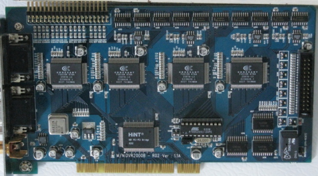
I've recently laid hands on a few Digi-Flower capture cards and found no indication that anyone has ever taken the time to poke at these cards with a digital multi-meter to discover how they are laid out. | |||
I have two versions, the DVR2000B-R02, and the DVR2510-MP2. | |||
[[Image:DVR2000B-th.jpg|Digi-Flower DVR-2000B-R02: 16 input; 4 Fusion BT878A chips]] | [[Image:DVR2000B-th.jpg|Digi-Flower DVR-2000B-R02: 16 input; 4 Fusion BT878A chips]] | ||
The DVR2000B has four Fusion bt878A decoders. The DVR2000B supports 16 composite inputs | |||
They both can support 16 composite inputs that are multiplexed through pairs of 74HC4051A Analog Multiplexer/Demultiplexers. Which of the 16 inputs is routed to any of the four bt878A's is controlled by GPIO pins. | They both can support 16 composite inputs that are multiplexed through pairs of 74HC4051A Analog Multiplexer/Demultiplexers. Which of the 16 inputs is routed to any of the four bt878A's is controlled by GPIO pins. | ||
| Line 131: | Line 133: | ||
* multiplexers are controlled by the lower 8 GPIO pins of the | * multiplexers are controlled by the lower 8 GPIO pins of the | ||
</pre> | </pre> | ||
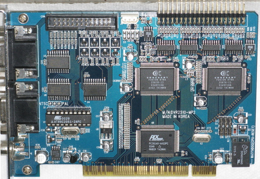
[[Image:DVR2510-th.jpg|Digi-Flower DVR-2510-MP2: 16 input; 2 Fusion BT878A chips]] | |||
The DVR2510 has two Fusion BT878A chips. Eight inputs are routed to each 878A chip, so only one M/D is needed for each 878A. The two additional M/D are used to route inputs to the composite out monitor connection. This card differs most from its larger cousin in that the Enable pins of the M/D's are connected to the Atmel micro-controller, so the card is not usable until the micro-controller has been initialized. | |||
Revision as of 19:45, 1 June 2010
I've recently laid hands on a few Digi-Flower capture cards and found no indication that anyone has ever taken the time to poke at these cards with a digital multi-meter to discover how they are laid out.
I have two versions, the DVR2000B-R02, and the DVR2510-MP2.
The DVR2000B has four Fusion bt878A decoders. The DVR2000B supports 16 composite inputs
They both can support 16 composite inputs that are multiplexed through pairs of 74HC4051A Analog Multiplexer/Demultiplexers. Which of the 16 inputs is routed to any of the four bt878A's is controlled by GPIO pins.
Each bt878A device controls a pair of M/D'ers:
      GPIO[0,1,2] => M/D[1][A,B,C] (select pins)
      GPIO[18]    => M/D[1][Enable]

      GPIO[0,1,2] => M/D[2][A,B,C] (select pins)
      GPIO[20]    => M/D[2][Enable]
When an input has been routed the signal is split between the bt878A's MUX0 and a 4581CS Sync Separator. As far as I can tell the only output of the 4581CS that is used is the Odd/Even field output that is routed to GPIO[15] on the respective 878A
                     74HC4051A
 Comp-In (1-8)  => M/D[1] (X0-7) -> \   [ L/C/R ] (inductor/
                                     |= [network] capacitor/
 Comp-In (9-16) => M/D[2] (X0-7) -> /             resistor)

               4581CS Sync Separator
   L/C/R     /  Comp-In -> Odd/Even  => GPIO[15]
 [network] =|
             \ 878A: MUX0
There is also a fifth pair of Mux/Demux chips that are used to send one of 16 inputs to an RCA jack via a 6db video amp. This routing function is controlled by an Atmel AT89C2051 (8051 family) micro controller. I have not determined how to talk to the micro controller at this time. The I2C pins of the first bt878A is connected to the serial port of the micro controller.
There is also a set of 8 external device I/O ports to send or receive On/Off signals from motion detectors or drive alarm circuits, and an on board WatchDog relay output. These are controlled by GPIO[3-10,12-13] of the first 878A.
More information on the Digi-Flower DVR2000B (DVR2510 is not listed here) cards available from Anko: http://www.anko-tech.com/products/df2000.htm
lspci data for the DVR2000B ( these numbers seem very generic.. how can the specific card be known?)
02:00.0 PCI bridge [0604]: Hint Corp HB6 Universal PCI-PCI bridge (non-transparent mode) [3388:0021] (rev 11)
03:0c.0 Multimedia video controller [0400]: Brooktree Corporation Bt878 Video Capture [109e:036e] (rev 11)
03:0c.1 Multimedia controller [0480]: Brooktree Corporation Bt878 Audio Capture [109e:0878] (rev 11)
03:0d.0 Multimedia video controller [0400]: Brooktree Corporation Bt878 Video Capture [109e:036e] (rev 11)
03:0d.1 Multimedia controller [0480]: Brooktree Corporation Bt878 Audio Capture [109e:0878] (rev 11)
03:0e.0 Multimedia video controller [0400]: Brooktree Corporation Bt878 Video Capture [109e:036e] (rev 11)
03:0e.1 Multimedia controller [0480]: Brooktree Corporation Bt878 Audio Capture [109e:0878] (rev 11)
03:0f.0 Multimedia video controller [0400]: Brooktree Corporation Bt878 Video Capture [109e:036e] (rev 11)
03:0f.1 Multimedia controller [0480]: Brooktree Corporation Bt878 Audio Capture [109e:0878] (rev 11)
I've been able to get the DVR2000B working with this patch on linux-2.6.24 kernel----
--- drivers/media/video/bt8xx/bttv.h.orig	2008-08-19 12:20:13.000000000 -0500
+++ drivers/media/video/bt8xx/bttv.h	2008-08-19 12:15:32.000000000 -0500
@@ -173,6 +173,7 @@
 #define BTTV_BOARD_VOODOOTV_200		   0x93
 #define BTTV_BOARD_DVICO_FUSIONHDTV_2	   0x94
 #define BTTV_BOARD_TYPHOON_TVTUNERPCI	   0x95
+#define BTTV_BOARD_DIGIFLOWER_DVR2000B     0x96

 /* more card-specific defines */
 #define PT2254_L_CHANNEL 0x10
--- drivers/media/video/bt8xx/bttv-cards.c.orig	2008-08-19 12:02:31.000000000 -0500
+++ drivers/media/video/bt8xx/bttv-cards.c	2008-08-19 12:52:58.000000000 -0500
@@ -81,6 +81,8 @@ static void tibetCS16_init(struct bttv *
 static void kodicom4400r_muxsel(struct bttv *btv, unsigned int input);
 static void kodicom4400r_init(struct bttv *btv);

+static void digiflower_dvr2000b_muxsel(struct bttv *btv, unsigned int input);
+
 static void sigmaSLC_muxsel(struct bttv *btv, unsigned int input);
 static void sigmaSQ_muxsel(struct bttv *btv, unsigned int input);

@@ -314,6 +316,7 @@ static struct CARD {
 	{ 0xd50018ac, BTTV_BOARD_DVICO_FUSIONHDTV_5_LITE,    "DViCO FusionHDTV 5 Lite" },
 	{ 0x00261822, BTTV_BOARD_TWINHAN_DST,	"DNTV Live! Mini "},
 	{ 0xd200dbc0, BTTV_BOARD_DVICO_FUSIONHDTV_2,	"DViCO FusionHDTV 2" },
+	{ 0x00000000, BTTV_BOARD_DIGIFLOWER_DVR2000B,	"Digi-Flower DVR2000B" },

 	{ 0, -1, NULL }
 };
@@ -3005,6 +3008,25 @@ struct tvcard bttv_tvcards[] = {
 		.tuner_addr     = ADDR_UNSET,
 		.radio_addr     = ADDR_UNSET,
 	},
+	[BTTV_BOARD_DIGIFLOWER_DVR2000B] = {
+		.name           = "Digi-Flower DVR2000B (master?)",
+		.video_inputs   = 16,
+		.audio_inputs   = 0,
+		.tuner          = UNSET,
+		.svhs           = UNSET,
+		.tuner_type     = TUNER_ABSENT,
+		.tuner_addr	= ADDR_UNSET,
+		.radio_addr     = ADDR_UNSET,
+		.no_gpioirq     = 1,
+		.gpiomask2      = 0x140007,
+		.muxsel         = { 2,6,10,14, 2,6,10,14, 2,6,10,14, 2,6,10,14 },
+		.muxsel_hook	= digiflower_dvr2000b_muxsel,
+                .gpiomux        = { 0, 0, 0, 0 }, /* card has no audio */
+		.no_msp34xx     = 1,
+		.no_tda9875     = 1,
+		.no_tda7432     = 1,
+		.pll            = PLL_28,
+	},
 };

 static const unsigned int bttv_num_tvcards = ARRAY_SIZE(bttv_tvcards);
@@ -4887,6 +4909,21 @@ static void kodicom4400r_init(struct btt
 	master[btv->c.nr+2] = btv;
 }

+/* DB1 = Top connector fan-out.  DB2 = Bottom connector fan-out. */
+#define DB1    0x100000
+#define DB2    0x040000
+
+static void digiflower_dvr2000b_muxsel(struct bttv *btv, unsigned int input)
+{
+	static const int masks[] = {
+		DB1,   DB1|1, DB1|2, DB1|3,
+		DB1|4, DB1|5, DB1|6, DB1|7,
+		DB2,   DB2|1, DB2|2, DB2|3,
+		DB2|4, DB2|5, DB2|6, DB2|7,
+	};
+	gpio_write(masks[input%16]);
+}
+
 /* The Grandtec X-Guard framegrabber card uses two Dual 4-channel
  * video multiplexers to provide up to 16 video inputs. These
  * multiplexers are controlled by the lower 8 GPIO pins of the
The DVR2510 has two Fusion BT878A chips. Eight inputs are routed to each 878A chip, so only one M/D is needed for each 878A. The two additional M/D are used to route inputs to the composite out monitor connection. This card differs most from its larger cousin in that the Enable pins of the M/D's are connected to the Atmel micro-controller, so the card is not usable until the micro-controller has been initialized.

